MetroLaser has developed a computational aero-optics test simulator (AOTS) code that models and simulates aero-optical effects on light propagating through an aerodynamic flow field. Useful for system evaluation, test planning and data interpretation, the code exploits the ability of computers to easily mimic random media and simulate the optical effects of turbulent boundary and shear layers. This enables computer simulation of optical propagation experiments through a wide range of random optical media. The user can determine with a few quick keystrokes typical aero optical parameters such as:
Strehl Ratio
Bore Sight Error
Point Spread Function
RMS Wavefront Error
Standard Deviations
Energy “in the Bucket”
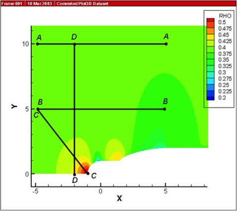
Figure 1 Generic turret and CFD solution showing beam paths.
AOTS can provide systems design and test engineers with a powerful, easy-to-use tool to complement other design tools. Intended to augment, not replace, CFD and experiment, AOTS accuracy improves as more experimental test and CFD data become available. In addition to providing designers and test engineers a way to compare and assess the importance of different aero-optical components in a flow field, AOTS can provide an a’priori guess at the result of a planned experiment to enable optimal pretest settings of instrument parameters, i.e., dynamic range and sensitivity. AOTS can even determine if a test is likely to be interpretable or even feasible, and ultimately can help with data interpretation. Finally, it can enable the aero-optical design engineer to quickly understand what changes can improve system performance.
Many attempts have been made to model and predict the optical effects of propagation through random media, using CFD as well as various turbulence models. Most available results are difficult to apply to practical problems, especially problems in aero optics. Recognizing that random media are relatively easy to set up computationally with algorithms that can mimic turbulent boundary and shear layers, we designed an algorithm, based on the physics of turbulent flow that complements and is integrated with CFD. This allows us to include high frequency effects that are not accommodated in current CFD codes. The code allows us to conduct simulated propagation experiments in a much wider range of realistic flows, much faster and easier.
AOTS assumes that the entire optical path from source to sensor can be divided into regions that are each characterized by a refractive index distribution, which can be further represented optically by a single phase screen that is positioned appropriately in the region of space that it represents. Once the phase screens and their locations are defined, an optical wave is propagated through the set of phase screens to determine the net effect on the wavefront at the sensor.
Typical Simulations
We run a wide range of computer experiments in which we provide sets of flow conditions and examine wavefronts that have passed through the sets. We anchored the code with experimental data. For example, statistical properties of such flows can be examined to determine how many runs are needed to converge on a stable mean Strehl ratio, wavefront deviation, and focus diameter. Individual realizations represent wavefront effects on pulsed lasers, averages represent effects on CW laser experiments, and time resolved realizations represent effects on such applications as laser communications. The user can quickly determine the importance of turbulence parameters and scale size distribution, how the size of turbulent eddies influence boresight error and Strehl ratio, how flow control can effect the aero optics. In some cases larger turbulent eddies cause the greatest aero-optical effects and the smaller eddies can be neglected.
Example AOTS result — We conducted experiments on a case of the flow field over a generic laser nose turret 2 meters in diameter with a 60 cm aperture being run at M = 0.85 at 35,000 ft.. To simplify the CFD part of the work, we produced a two-dimensional solution from WIND about an axisymmetric body, then obtained the three-dimensional grid by rotating the solution 360 degrees about the axis of symmetry, which shows the two-dimensional density solution for this case. The turret has a one-meter radius. Using the procedure described above, we propagated light waves along various paths, as shown in Figure 1, wherein ray C is at a 45 degree angle with the axis, ray D is perpendicular to the axis, and rays B and A are parallel to the axis. Ray A is furthest from the influence of the turret and represents the least disturbed case. 100 light rays covering the aperture represented each light wave.
As the light wave is propagated, each ray is phase delayed by the refractive index field, which is determined by the density field. This provides a phase screen for the aero-optical simulator that is defined by the 100 phase values. The phase screen is placed near the surface of the model, and the wavefront can then be completely analyzed in terms of its focusing parameters and Strehl ratio. Moving the wavefront farther into the flow field causes severe wavefront deterioration, as we can see in Figure 2.
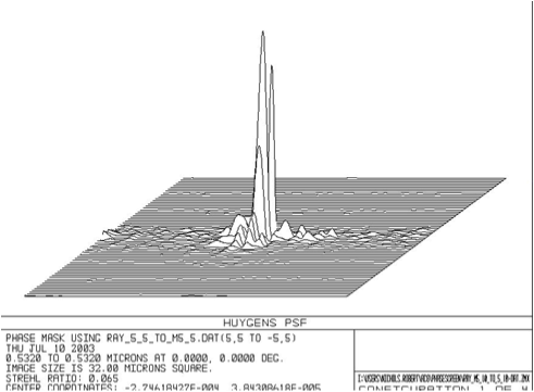
Figure 2- Results of propagation of a light wave parallel to the model axis through its flow field along path BB.
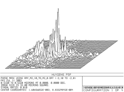
Figure 3 – Results of propagation of a light wave (DD) perpendicular to the model axis through its flow field.
Figure 3 shows the point spread function for the path “B-B” of where the Strehl ratio drops to 0.065. A 10-meter long path ending at a region of a high pressure gradient path “D-D” is tangent to some of the highest pressure regions of the computational data set.
The Strehl ratio drops even further to a value of 0.01 with a point spread function shown in Figure 3. The focused spot now is aberrated unsymmetrically as would be expected.
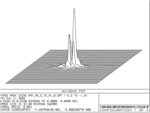
Finally, we propagate at 45 degrees to the axis of the model through the region of greatest density contours. The resulting PSF shown in Figure 4 has a Strehl ratio of 0.083. This beam has a shorter pathlength than the other cases, being 6.4 meters.
Figure 4. Results of propagation of a light wave (CC) at 45 degrees to the model axis.
These results show that we can interface the CFD with the aero optics code automatically. Each of these results are arrived at in seconds of run time so that an operator can run many experiments and anticipate the effects of a wide range of propagation paths and flow conditions.
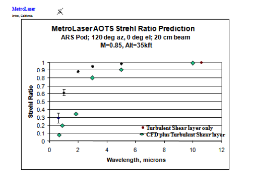
Other Examples — Other examples include propagation through various turbulent boundary and shear layers and effects of flow control and wavelength. Figure 5 and Figure 6 illustrate the effect of wavelength on the focused beam. The former, a PSF for visible light, suggests considerable deterioration, while the latter shows the improvement in Strehl ratio with increase in wavelength. More details and examples have been published in AIAA-2004-0471
Aero-optics is the science that deals with (usually unwanted) effects on an electromagnetic wavefront caused by aerodynamics. These wavefront effects are caused by refractive index variations that occur in aerodynamic flow fields and distort the wavefront by delaying or advancing parts of it by different amounts. For most gases, index-of-refraction fluctuations are proportional to the fluid density fluctuations through the Gladstone-Dale constant.
Many types of optical systems (i.e., designators, rangers, LIDAR, laser communicators, directed energy weapons) receive or project light through an aerodynamic flow field, which effectively inserts an unwanted, time-varying, optical element into the system leading to loss of resolution, bore sight error, tracking error, reduction in signal to noise, and reduced energy density on a target. The capability of almost all of these devices is deteriorated by aero-optical effects on the optical wavefront caused by flow features of the aircraft, such as shear and boundary layers. These problems have been observed in many flight and wind tunnel tests since the early years of testing of airborne lasers.
Figure 5-Point Spread Function of a single realization through a turbulent shear layer.
Figure 6-Strehl Ratio as a Function of Wavelength through a Turbulent Wake